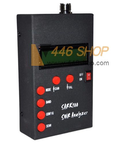
Mini HF ANT SWR Antenna Analyzer Meter For Ham Radio Hobbists New
Hardware:
Precise and self-calibrating reflectometer design measures forward and reflected signals and impedance data
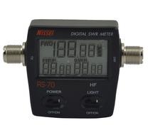
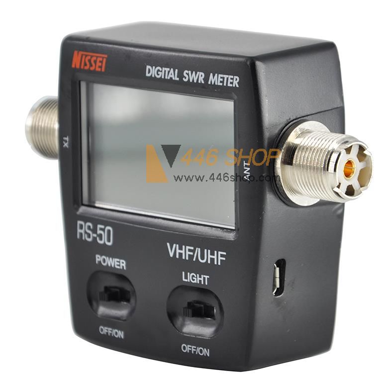
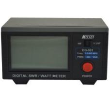
Display 2x16 with optional backlight
Precision DDS signal generator (AD9851) used as signal source
USB port connects to PC for field-upgradeable software and uploading of real-time measurement data
Buzzer
Operation:
Manual control option displays SWR and complex impedance at selected frequencies
Automatic scanning results displayed as frequencies of lowest SWR and complex impedance
Battery operated for field use or use external 13.8V wall adaptor
Power saving modes
Multi-point calibration for better accuracy
Instrument Capabilities:
Measure antenna electrical parameters: SWR, impedance (resistance + reactance), capacitance, inductance
Measure feedpoint impedance
Measure ground loss
Adjust antenna tuners and determine loss
Measure inductors and capacitors
Measure coax transmission line (SWR, length, velocity factor, approximate Q and loss, resonant frequency, and impedance)
Measure and determine optimum settings for tuning stubs: SWR, approximate Q, resonant frequency, bandwidth, impedance
Determine characteristic impedance of transmission line
Determine length of ¼ and ½ wave phasing lines
Coaxial Cable Loss
Determine antenna tuner loss
Measure balun loss
Measure inductor Q
Estimate quartz crystal parameters
Measure magnetic loop resonance and SWR
SPECIFICATIONS
Frequency Generation & Control:
1 - 60 Mhz
Source impedance: 50 Ohms
Stability: +/- 100 ppm
Spectral Purity: Harmonics down >- TBD dB beyond 60 MHz
Step Size: User configurable increments of 100 Hz, 1 kHz, 10 kHz, and 100 kHz
Usable Measurement Range:
SWR: 1.0 to 9.99
Impedance: approx. 5 to 2000 ohms
RF Output:
Adjustable: 2.0 Volts pp (typ)
Power supply:
3.7v li-on battery
External: 12 to 14 Volts DC, 500mA
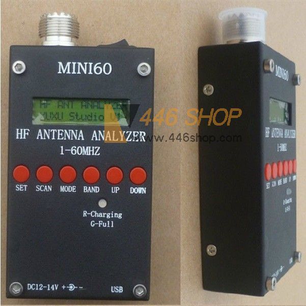
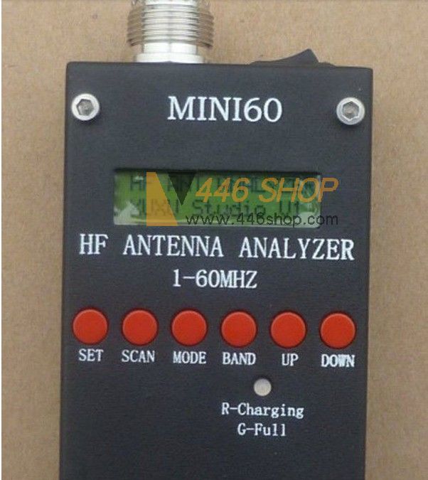
Controls:
Pushbuttons (5): "Mode", "Band", "Config", "Scan", "Up", "Down"
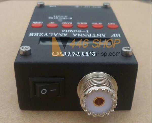
Switch: "Power On"
Connectors:
RF Out: BNC
USB: Mini-B receptacle
External power: 2.1mm Power Jack (center pin positive)
Description:
1. Frequency Generation&control:1-60MHz
2. Source impedance:50Ohms
3. Stability:±100ppm
4. Spectral Purity:Harmonics down-TBD dB beyond 60MHz
5. Step size:User configurable increments of 100Hz,1KHz,10kHz,and 100KHz
6. Usable Measurement range:SWR 1.0-9.99
7. Impedance:approx 5-2000ohms
8. RF output:Adjustable 2.0volts pp(typ)
9. Control:”Mode” “Band” “config” “scan” “up” “down”
10. Switch:Power on
11. Connectors:RF
12. USB:Mini-B receptacle
13. External power:2.1mm power jack
Application:
1. Measure antenna electrical parameters:SWR impedance(Resistance+reactance),capacitance,inductance
2. Measure feedpoint impedance
3. Measure ground loss
4. Adjust antenna tuners and determine loss
5. Measure inductors and capacitors
6. Measure coax transmission line(SWR,length,velocity factor,approximate Q and loss,resonant frequency,and impedance)
7. Measure and determine optimum settings for tuning stubs:SWR,approximate Q ,resonant frequency,bandwidth,impedance
8. Determine characteristic impedance of transmission line
9. Coaxial Cable Loss
10. Determine antenna tuner loss
11. Measure balun loss
12. Measure inductor Q
13. Estimate quartz crystal parameters
14. Measure magnetic loop resonance and SWR
Operation button deginitions:
1.Mode:selects operation mode:impedance (default),complex impedance, capacitance, and inducatance
2.BAND:select band from any of the available bands:160M to 6M
3.CONFIG:Provides menu for configurations and extended functions: PC link, step size setting, suspend timeout setting, calibration, and software upgrade
4.SCAN:Pressing this control initiates a scan of frequencies of the selected BAND, Scan exits to impedance mode showing the 2:1 bandwidth and resonant point the antenna
5.CAN(up):increase frequency and used to cancel operation for CONFIG menu
6.VAL(down):decrease frequency and used to validate operation for CONFIG menu
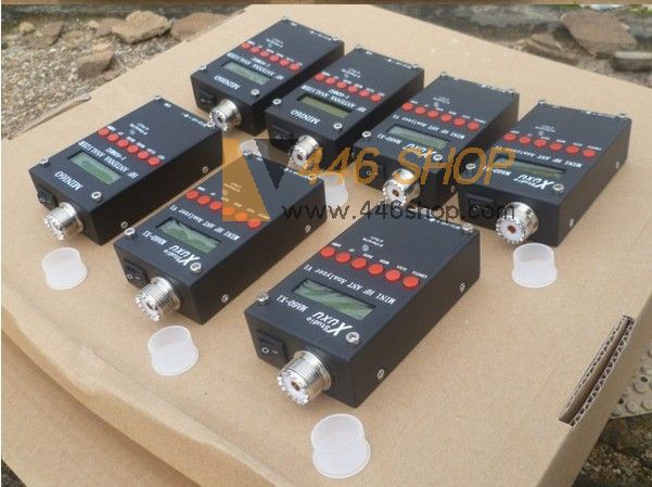
Package includes:
1 x PC Antenna Analyzer
If bulk order, please contact Ms. Amy Huang for the wholesale price:
Tel: 86(592)2653580
Fax: 86(592)3720556
SKYPE: amy.446shop
Email: amy@446shop.com
| 

 Chinese
  Français
 Deutsch
 English
  Español
 Português
 اللغة العربية


 Bank Transfer